
|
Installation Instructions for Model 50 and 100 Zinc Conductor Weights |
 |
|
BARE CONDUCTOR INSTALLATION INSTALLATION OVER CONDUCTOR
PROTECTION DEVICES |
 |
|
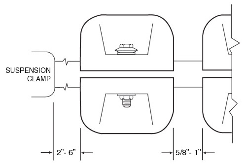
SERIAL INSTALLATION When two or more weights are required on a conductor on the same side of the sus-pension clamp, space the weights approximately 5/8” to 1” apart to avoid any possibility of contact between them. Installed weight contact might cause sharp protrusions with resulting corona emissions. |
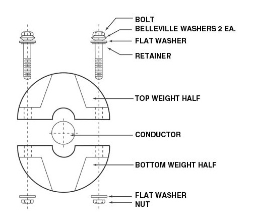
| ASSEMBLY
INSTRUCTIONS FOR ZINC CONDUCTOR WEIGHTS |
| 1. | Place one weight half on the conductor. |
| 2. | Bring the other half into position and drop the two bolt washer assemblies into place. |
| 3. | Slip a flat washer onto each bolt followed by a nut. |
| 4. | Snug up the nuts and check the alignment of the weight halves. |
| 5. | Torque the nuts to (30-35 lb./ft. for Model 50 Weights), (35-40 lb./ft. for Model 100 Weights). |
 |
| CONTACT US BY E-MAIL |
NH INDUSTRIES
1003 E. 75th Ave.
Denver, CO 80229
Tel: 1- 303-287-6634
Fax: 1-303-287-0081