
More About ZC Weights
 |
 |
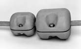
100
lb. ZC Weight |
50
lb. ZC Weight |
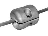
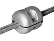
ZC weights are specifically designed to be installed on electrical conductors as are generally found on transmission lines. The design is such that the weights are clamped onto either the armor rods or bare conductor close to the point of suspension. Special High Grade zinc is used to cast ZC weights. This offers the optimum combination of corrosion resistance, density, and galvanic activity characteristics desirable in the application for which they were designed. Environmental and safety concerns are of low order when using this product. Special High Grade zinc purity is such that only traces of impurities are permitted. Impurity concentrations at or below 0.003% are required to meet the standard for this zinc grade. ZC weights qualify as an item under current OSHA regulations. As such it requires no labeling or hazard communication. (See OSHA Regulations, Standards-29 CFR, Hazard Communication .-1910.1200, Section (b) (6) (V), paragraph (C).). Should any operations such as machining, grinding, etc. be performed on the parts after shipment by the manufacturer, consult the appropriate OSHA guidelines and regulations. ZC weights should be given consideration as a relatively simple and economical solution to several problems that may arise during line design and construction and to correct some unsatisfactory conditions on existing lines. The use of ZC weights should be evaluated where there is an uplift condition instead of a more expensive dead-end or high suspension structure. Uplift conditions may occur when spotting structures on a new line, when reconductoring, or when relocating as for highways or other developments. They may also be used at a dead-end tower where there exists a severe uplift condition and the bracing for the arm is not designed for this compressive load. ZC weights are highly applicable to use on the jumper string at a dead-end structure. They place sufficient tension on the insulator string to eliminate R.I.V. due to poor contact between the ball and socket of the insulators and facilitate the forming of the jumper wire. The increasing importance of esthetics makes the placement of structures on hill tops that show on the skyline a cause for criticism from many groups. Maintaining a low profile, however, can necessitate the use of many dead-end or very high suspension structures. In many instances such as these, the use of ZC weights can be of significant economic value. When using ZC weights at tangent or small angle structures, treat the point of installation as a dead-end and place the aeolean vibration dampers at the other end of the span. Should the weights be used on consecutive structures, consult your vibration damper supplier for placement recommendations. Due to the small size of the weights, they will normally lie within the energized area which the transmission engineer has used for conductor swing clearance to the supporting structure. ZC weights can therefore be used on the standard tangent or small angle structure to maintain the design H/V with no decrease in conductor-to-structure clearance. The weight/volume ratio, together with its nonmagnetic properties make zinc a most suitable material for use in a conductor weight. Being nonmagnetic eliminates any hystresis and eddy current losses. Such losses, with the large currents carried by many transmission lines, could cause excessively elevated temperatures in the conductor at the point of attachment. This power loss during the life of the line will become economically significant as shown in studies comparing nonmagnetic with ferrous materials used for line hardware. This economic factor holds true even in those cases where current values are not great enough to cause an excessive temperature rise in ferrous hardware.(1, 2) The round design and large radius ends of ZC weights, together with all fastening hardware being recessed into the weight body enables the weight itself to contribute nothing to the R.I.V. and corona emission when installed on the line. This design has been used on 765 kV lines. Where conditions indicate, ZC
weights are completely suitable for serial installation on Identical halves, clamped together over the conductor or armor rods make up each ZC weight. Clamping is accomplished by means of two stainless steel bolts, one bolt for each side of the weight. Loss of clamping force is prevented through the use of "Belleville" type spring compression washers Two compression washers are used on each bolt, one each under the bolt head and the nut. These compression washers then bear on flat, stainless steel washers to provide uniform assembly torque values and to maintain the clamp load over the life of the line. ZC weights are specifically dimensioned and fabricated for each particular conductor or armor rod application. This requires that the diameter of the conductor or armor rod upon which the weight is to be installed be shown on the request for quotation and must appear on all purchase orders. ZC weights are designed to be
readily sized to any conductor diameter required. Each weight half is cast blank, with no
conductor groove. The blanks are then machined to the desired I.D. This I.D. is then
stamped on the flat side of each casting. The two cavities permit them to be sized to a
wide range of conductor diameters with a minimal variation in weight. This weight
variation is 4.8% for a weight machined to it's maximum design diameter. The largest
diameter conductor for which the weights are designed is 2 3/4" (7 cm) for the fifty
pound, and 3 1/2" (8.9 cm) for the one hundred pound weights. |
NH INDUSTRIES
1003 E. 75th Ave.
Denver, CO 80229
Tel: 1- 303-287-6634
Fax: 1-303-287-0081
 the conductor in order to achieve the total weight
required. It is recommended that where two or more weights are used at one location in
series, a space of one half inch to five eighths inch be maintained between each weight.
Model 50 and Model 100 weights may be combined as needed in such installations.
the conductor in order to achieve the total weight
required. It is recommended that where two or more weights are used at one location in
series, a space of one half inch to five eighths inch be maintained between each weight.
Model 50 and Model 100 weights may be combined as needed in such installations.